2.0. Overview
The Properties window allows you to configure various settings, including the incident source, detector configuration, parameters for integration, and post-integration behavior. Each setting item is selected using the tabs on the left.
2.1. Source Settings
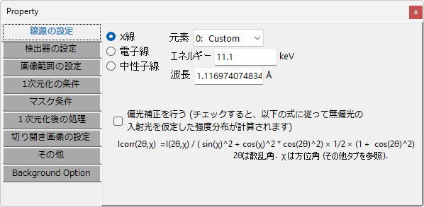
This tab configures the type and energy of the incident beam.
Source Type and Energy
X-ray
For a tube source, select the element and the transition line (K-line, L-line, etc.). The wavelength and energy are automatically filled in. For synchrotron radiation, select 0:Custom and enter the appropriate wavelength or energy.
Electron beam
Enter the energy or wavelength. If you enter the energy, the relativistically corrected wavelength is automatically filled in.
Neutron beam
Enter the energy or wavelength.
Polarization Correction
This feature is only active when X-ray is selected. If the incident X-ray is linearly polarized in a specific direction, this function applies an intensity correction according to the given formula, as if unpolarized X-rays were used.
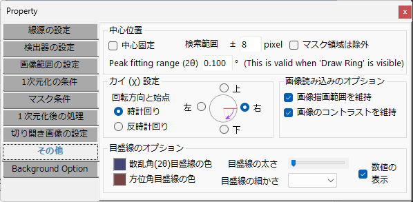
For synchrotron radiation, the X-rays are strongly polarized, so it is recommended to enable this option. Additionally, depending on the detector orientation, the polarization direction may differ, in which case you should set the starting point of χ (azimuthal angle) in the “Others” tab.
2.2. Detector Settings
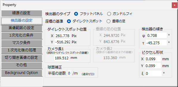
This tab configures the detector type and the geometric arrangement of the detector relative to the sample and the incident beam.
Detector Type
Select whether the detector is a flat panel detector (Flat panel) or an annular Gandolfi camera (Gandolfi).
Coordinate Reference
Select exclusively whether to use the “Direct spot” mode or the “Foot of perpendicular” mode for defining the geometric arrangement of the detector. The terminology definitions are the same as in ReciPro. Please also refer to this page.
The former defines the geometric arrangement of the detector by:
- The coordinates of the intersection of the incident beam and the detector (direct spot position)
- The distance between the direct spot and the sample (camera length 1)
The latter defines the geometric arrangement of the detector by:
- The coordinates of the foot of the perpendicular from the sample to the detector (foot of perpendicular position)
- The length of that perpendicular (camera length 2)
to define the geometric arrangement of the detector.
In Direct Spot Mode
Direct Spot Position
Specify the direct spot position in pixel units. If the direct spot is visible in the image, it can be obtained using the “Center position” tool in the Main Window.
Camera Length 1
Specify the distance between the sample and the direct spot in mm.
In Foot of Perpendicular Mode
Foot of Perpendicular Position
Specify the coordinates of the foot of the perpendicular from the sample to the detector in pixel units.
Camera Length 2
Specify the length of the perpendicular from the sample to the detector in mm.
Detector Tilt
Configure the tilt of the detector. For the definitions of Φ and τ, please refer to this page.
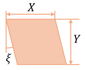
Pixel Shape
Configure the size (unit: mm) and distortion angle of the pixels that compose the image. X, Y, and ξ are defined as shown in the following figure.
When using a CCD or CMOS detector, the pixel shape is controlled by the semiconductor fabrication process, so use the catalog values directly for X and Y. The value of ξ can be set to zero.
When using an Imaging Plate (IP), the values of X and Y may deviate slightly due to aging of the IP reader, and ξ may not be zero. Since it is difficult to determine these values manually, please use the IPAnalyzer parameter calibration tool.
Spherical Correction
Configure this only if the detector is deflected on a spherical surface and correction is needed.
2.3. Image Range Settings
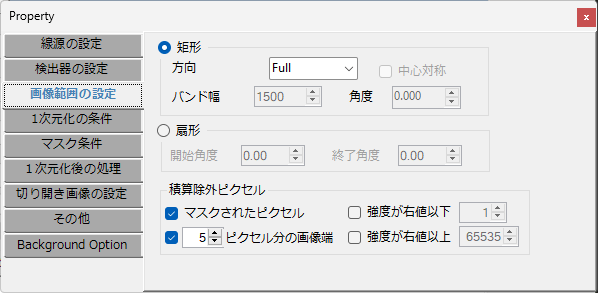
This tab configures the calculation target region in the image.
Rectangle
To restrict the integration region within the IP image to a rectangle, select the Rectangle radio button. In this mode, the integration range is set as a rectangle. You can input the size, width, and angle of the rectangle.
Direction
Select the direction of the integration rectangle.
Band Width
Select/enter the width of the rectangle when a direction other than Full is selected in “Direction”.
Center Symmetry
This becomes active when Free is selected in “Direction”. When checked, the rectangle is made centrosymmetric.
Angle
This becomes active when Free is selected in “Direction”. The rectangle direction can be set to any arbitrary angle.
Sector
To restrict the integration region in the image to a sector, select this button. The angle starts at 0° toward the right of the screen and proceeds clockwise.
Start/End Angle
Enter the start/end angles of the sector.
Excluded Pixels from Integration
In addition to the region restrictions above, you can specify pixels to exclude from the calculation.
Masked Pixels
When checked, the cyan-colored pixels selected via “Spot detection” or manual spot mode are excluded from integration.
Intensity Above/Below the Specified Value
Pixels (displayed in blue) with intensity below (or above) the specified value are excluded from integration.
# Pixels Width from Edge
Excludes a region of the specified number of pixels from the top, bottom, left, and right edges of the image from integration.
2.4. Integration Conditions
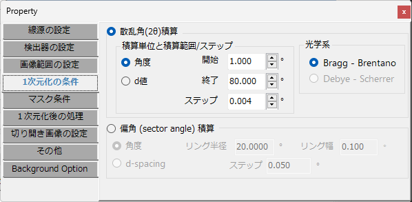
Configure the start/end positions and step size for the integration profile. The two-dimensional diffraction pattern is integrated into a one-dimensional profile according to these settings.
Scattering Angle (2θ) Integration
When this is checked, the intensities distributed concentrically from the center are integrated to calculate an intensity profile with the scattering angle as the horizontal axis.
Angle / d-value
Set the horizontal axis to diffraction angle (2θ) or d-value.
Start, End, Step
Set the start, end, and step size in the unit selected for the horizontal axis.
Sector Angle
When this is checked, integration is performed along the circumference of a “ring-shaped region with a width”. Note that this is a completely different calculation from the standard scattering angle measurement. This mode is used, for example, when you want to observe the intensity distribution along the circumferential direction of a single Debye ring.
Angle / d-value
Specify whether the unit defining the “ring-shaped region with a width” is angle or d-value.
Ring Radius / Ring Width
Specify the radius and width of the ring.
Step
Specify the step for dividing the circumferential direction of the ring. The intensity distribution is calculated at the specified step, starting from 0° toward the right and proceeding clockwise.
Optical System
- Bragg-Brentano: Converts the intensity to correspond to the Bragg-Brentano optical system.
- Debye-Scherrer: Not yet implemented
2.5. Mask Conditions
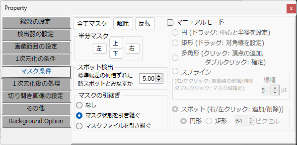
Configure mask application to specific regions, inversion, spot detection precision, mask inheritance settings, and manual mask mode settings.
Mask All / Clear All / Invert Buttons
Mask all pixels, clear all masks, or invert the mask state for all pixels.
Half Mask
Mask the top, bottom, left, or right half of the image.
Spot Detection
Specify the threshold for “Spot detection” performed in the Main Window.
Mask Inheritance
If “Inherit mask state” is selected, the mask state set for the previous image will also be applied to the new image.
On the other hand, if “Inherit mask file” is selected, the mask state set for the previous image is discarded, but if a mask file was loaded for the previous image, that file will also be applied to the new image.
Manual Mode
When Manual mode is checked, you can set masks of various shapes by mouse operations in the image drawing area of the Main Window. Note that the following descriptions correspond to operations using the left mouse button. Performing the same operations with the right button will erase the masked region.
Circle
Drag the mouse button in the image drawing area of the Main Window to specify and mask a circular region.
Rectangle
Drag to specify the diagonal of a rectangular region and mask the area within that rectangle.
Polygon
Click to specify vertices sequentially to define a polygon, then mask the area within the polygon. After specifying the last vertex, double-click to confirm (the double-clicked point is not added as a vertex).
Spline
Click to specify control points sequentially to mask the region through which a smooth spline curve with a width passes through the control points. After specifying the last control point, double-click to confirm (the double-clicked point is not added as a control point). The width of the curve is specified in pixel units.
Spot
Mask a circular or rectangular region of a specified size.
2.6. Post-Integration Processing
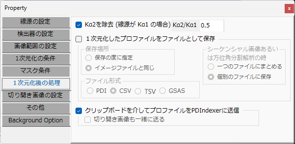
Configure what actions to perform after executing “Integration” in the Main Window.
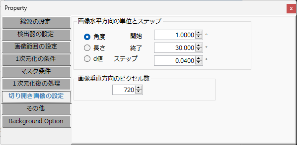
2.7. Unfolded Image Settings
2.8. Others