A.1.1. Overall Coordinate System (excluding the Diffraction Simulator)
Definition of Axes
ReciPro handles various “directions,” so their definitions are explained here.
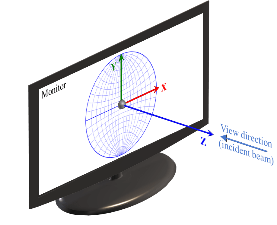
As shown in this figure, ReciPro adopts a right-handed coordinate system where:
- The X-axis points to the right of the monitor screen
- The Y-axis points upward on the monitor screen
- The Z-axis points perpendicularly toward the viewer from the monitor screen
The direction of the beam (Incident beam) and the viewing direction (View direction) looking at the monitor coincide, corresponding to the -Z axis.
Most calculations performed in ReciPro only involve directions (i.e., 3×3 rotation matrices), and there is no need to be aware of the position of the origin. However, in the “Diffraction Simulator” window, the origin position must be explicitly considered. See A.1.2. for details.
Initial Crystal Orientation
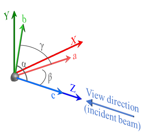
ReciPro defines the initial state of crystal orientation (the state at first startup or after pressing Reset rotation) as shown in the figure1. Specifically:
- The c-axis is aligned with the Z-axis direction
- The b-axis lies on the YZ plane, oriented close to the Y-axis
- The a-axis is determined by the b and c axes (right-handed coordinate system)
In other words, the direction toward the viewer from the monitor coincides with the [001] zone axis, and the rightward direction of the monitor coincides with the normal of the (100) crystal plane. The c-axis (= [001] zone axis) always coincides with the Z-axis, but note that in some crystal systems, a and b do not necessarily coincide with X and Y2.
Euler Angles
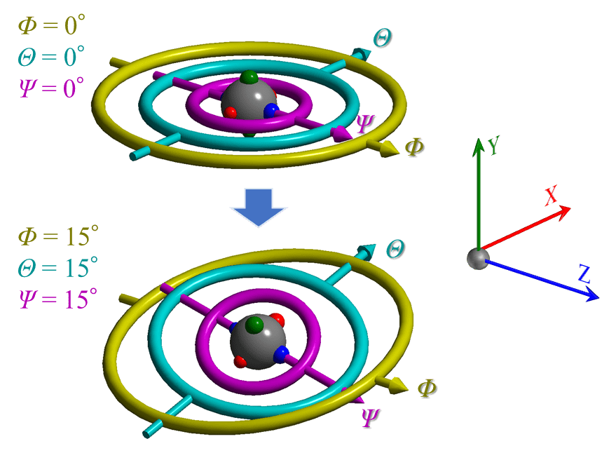
In ReciPro, the crystal can be rotated in various directions. Euler angles are used to express this crystal orientation.
The Euler angles in ReciPro use three symbols: Φ, θ, Ψ, as shown in the figure. As illustrated in the upper part of the figure, when the angles Φ, θ, Ψ are all zero, the directions of their corresponding rotation axes coincide with Z, X, and Z, respectively3.
Note that the three Euler angles have a hierarchical relationship. Φ is the highest-order (1st) rotation, followed by θ (2nd). Ψ is the lowest-order (3rd) rotation. The direction of a lower-order rotation axis changes depending on the state of the higher-order rotations4. As an example, the lower part of the figure above shows the state where Φ, θ, Ψ are all set to 15°. The rotation axis corresponding to angle Φ always coincides with the Z-axis, but the rotation axes corresponding to angles θ and Ψ generally do not coincide with any of X, Y, or Z.
A.1.2. Coordinate System Definition in the Diffraction Simulator Window
The Diffraction Simulator simulates diffraction patterns projected onto a detector plane and displays them on the monitor. The detector is a finite-sized plane formed by a collection of pixels, placed at a certain distance from the sample (scatterer). Furthermore, this detector may be tilted with respect to the incident beam. To accurately simulate such situations, information about the geometric relationship between the detector and the sample, as well as the pixel size and number of pixels, becomes important.
When the detector is not tilted
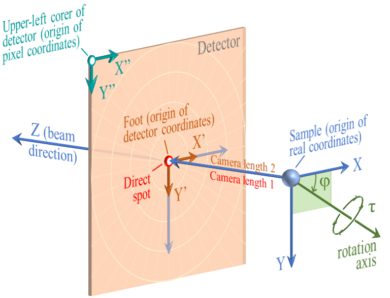
First, consider the situation shown in this figure, where the detector is not tilted (the incident beam and the normal of the detector plane are aligned).
The point where the beam intersects the detector is called the Direct spot, and the distance from the sample to the Direct spot is defined as Camera length 1 (C1). On the other hand, the distance from the sample to the foot of the perpendicular dropped from the sample onto the detector (Foot) is defined as Camera length 2 (C2). When the detector is not tilted, the Direct spot and the Foot coincide, and Camera length 1 and Camera length 2 are equal.
Real coordinates is a three-dimensional Cartesian coordinate system with the sample as the origin, in units of mm. The Z-axis always coincides with the beam direction (note that this differs from the definition in A.1.1.5). The X-axis direction is to the right when facing the Z-axis direction, and the Y-axis direction is downward.
Detector coordinates is a two-dimensional coordinate system with the Foot as the origin, in units of mm. The rightward direction on the detector plane is the X’-axis, and the downward direction is the Y’-axis.
Pixel coordinates is a two-dimensional coordinate system with the upper-left corner of the detector as the origin, in units of pixels. The rightward direction is the X”-axis, and the downward direction is the Y”-axis.
When the detector is tilted
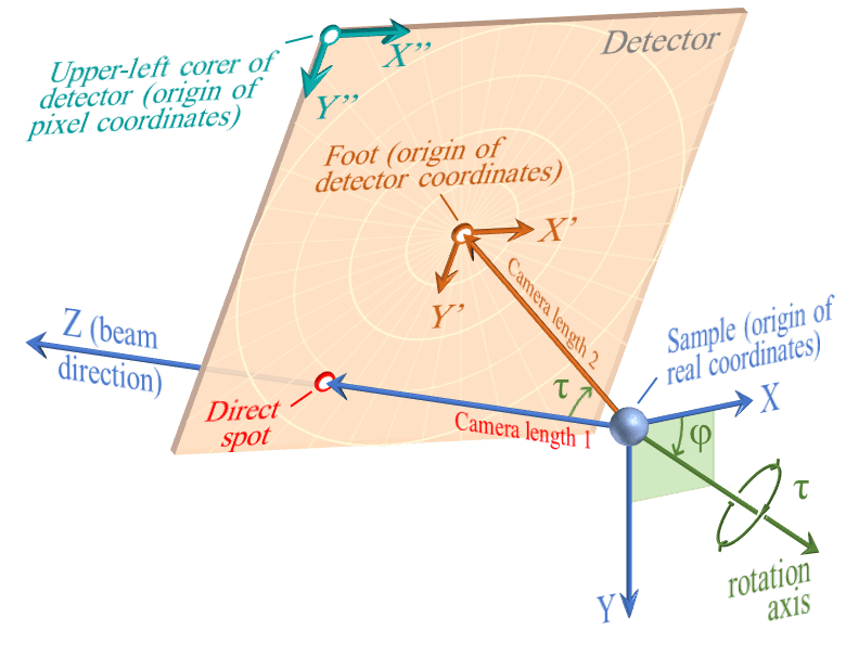
Next, consider the situation where the detector is tilted.
To express the tilt of the detector, two parameters are introduced: the direction of the rotation axis (φ) and the rotation amount (τ). The rotation axis is considered to lie on the XY plane (Z=0 plane), and φ is the angle from the X-axis. Then, a rotation of τ in the right-hand screw direction is performed around the rotation axis defined by φ.
As a result of the rotation operation defined by φ and τ, the detector becomes tilted and the Direct spot and the Foot no longer coincide6. To reiterate, the distance from the sample to the former is defined as Camera length 1 (C1), and the distance to the latter as Camera length 2 (C2)7. Note that the origin of the detector coordinate system is always the “Foot,” and the origin of the pixel coordinate system is always the upper-left corner of the detector. Also note that when the detector is tilted, the directions of X, Y and X’, Y’ do not coincide.
Note that even when the detector is tilted, the ReciPro diffraction simulator always displays the detector plane. In other words, the viewing direction and the incident beam direction do not coincide. Please be aware of this potentially confusing point.
Geometric Parameters
Rotation of Detector
The rotation state of the detector is defined by the rotation operation defined by φ and τ. This rotation axis passes through the origin of the real coordinate system (i.e., the sample) and lies on the XY plane.
φ
The angle between the X-axis and the rotation axis. When zero, it coincides with the X-axis. The positive direction of the angle is the right-hand screw rotation direction advancing along the Z-axis.
τ
Indicates the rotation amount. In the right-hand screw direction.
Detector Coordinates (X’, Y’)
A two-dimensional Cartesian coordinate system on the detector plane, in units of mm. The origin of this coordinate system is the Foot. The rightward direction facing the detector is defined as the X’-axis, and the downward direction as the Y’-axis. When the detector is not tilted, the X’-axis and Y’-axis coincide with the directions of the X-axis and Y-axis of the real coordinate system. Also, they are always parallel to the X”-axis and Y”-axis of the pixel coordinate system described below.
Foot
The position of the foot of the perpendicular dropped from the sample onto the detector plane. This is the origin of the detector coordinate system. If the detector is not tilted, it coincides with the position of the Direct spot.
Camera Length 1 (C1)
The distance from the sample to the Direct spot. The unit is mm.
Pixel Coordinates (X”, Y”)
A two-dimensional Cartesian coordinate system on the detector plane, in units of pixels. The rightward direction facing the detector is the X”-axis, and the downward direction is the Y”-axis. The origin is always the upper-left corner of the detector.
Pixel Size
The length of one side of a pixel. The unit is mm. Only square pixel shapes are supported.
Detector Width/Height
The size (width and height) of the detector. In units of pixels.