4.0. Overview
Stereonet projection is a method of mapping points on a unit sphere to a plane.
This feature projects the orientations of crystal planes and axes with arbitrary indices onto a stereonet.
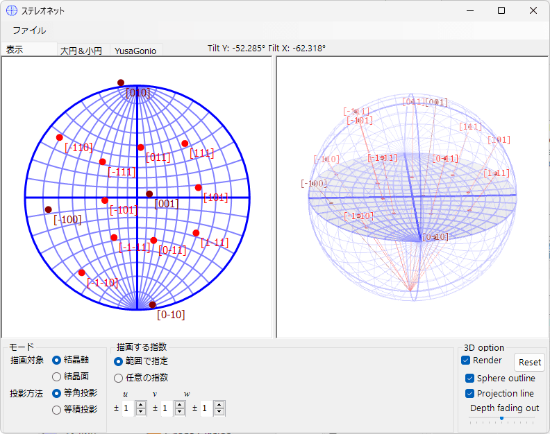
4.1. Main Area
The central area displays the stereonet projection of the crystal planes and crystal axes for the selected crystal.
Mouse Operations
The following mouse operations are available:
- Left drag: Rotate the crystal
- Right drag: Zoom in
- Right click: Zoom out
- Left double-click: Toggle projection method
When you rotate the crystal by left-dragging, the rotation state of all windows is updated through the main window.
Also, when you move the mouse, the “Tilt X, Y” angles corresponding to latitude and longitude are displayed at the top of the screen.
4.2. File menu
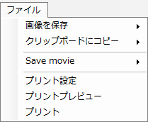
Save the displayed stereonet to a file or copy it to the clipboard.
You can also save an animation with a specified rotation axis and rotation speed.
4.3. Mode
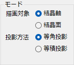
Drawing Target
Select the drawing target (crystal axes / crystal planes).
Projection Method
Select the stereonet projection method.
Equal-Angle Projection
This is the so-called Wulff net. It is a projection method that preserves angular relationships. However, area (solid angle) is not preserved.
Equal-Area Projection
This is the so-called Schmidt net. It is a projection method that preserves area (solid angle), but angular relationships are not preserved.
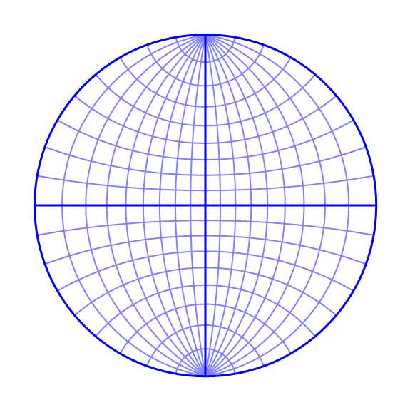
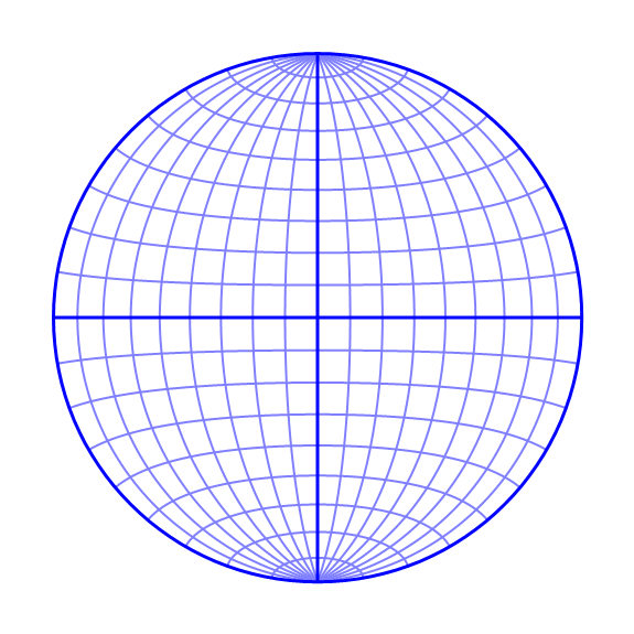
Below, the stereonet outlines for the equal-angle and equal-area projection cases are shown. In the equal-angle projection, meridians and parallels always intersect at right angles, but you can see that the area for the same solid angle changes between the center and the periphery of the stereonet. On the other hand, in the equal-area projection, there is no change in area, but you can see that angular relationships are not preserved.
Equal-Angle Projection
Equal-Area Projection
4.4. Indices
Set the crystal planes / zone axes to be drawn.
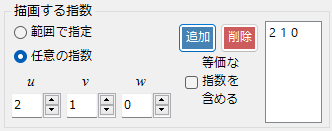
Specify by Range
In this mode, you specify the range of uvw or hkl indices.
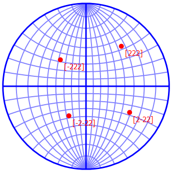
Arbitrary Indices
In this mode, you specify crystal planes / zone axes with specific indices. After setting the indices, press the “Add” button to add them to the drawing list. Press the “Delete” button to remove them. Checking “Include equivalent indices” will draw all crystallographically equivalent crystal planes / zone axes.
4.5. Tab Menu
Display
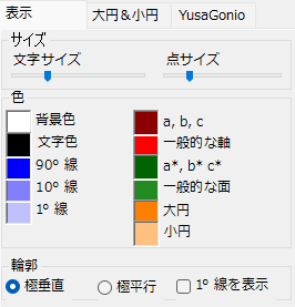
Size
Specify the size of points and text. Adjustable using sliders. The text size adjusts the size of the indices shown next to the points on the stereonet. The point size adjusts the size of the points on the stereonet.
Color
Set the colors of points, text, stereonet outline, etc.
Outline
Specify how the stereonet outline is displayed.
Great Circle
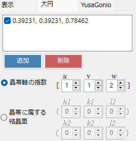
A great circle is the curve (circle) formed by the intersection of a plane passing through the center of a sphere with the sphere surface. For example, the equator and meridians are types of great circles. To define a great circle, you need to specify either a direction perpendicular to points on the great circle (i.e., the polar direction) or two points on the great circle. In crystallography, the former (polar direction) is called a “zone axis,” and the set of orientations on the great circle is called a “zone.”
To draw a great circle, specify the orientation of the great circle using one of the two options below and click “Add.” To remove a great circle, click “Delete.”
Zone Axis Indices
Specify the great circle by the indices of the zone axis.
Crystal Planes Belonging to the Zone
Specify by the indices of two crystal planes belonging to the zone.
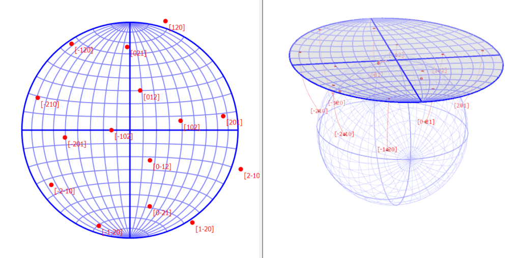
4.6. 3D Rendering
When you check “3D Rendering,” a control that visually represents the stereonet projection method in three dimensions is displayed, along with the following options.
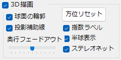
Reset Orientation
Resets the drawing orientation (not the crystal orientation).
Sphere Outline
Displays the outline of the sphere.
Projection Guide Lines
Displays the projection guide lines.
Depth Fade-Out
Adjusts the depth fade-out effect.
Index Labels
Displays index labels.
Hemisphere Display
Displays only the projection target points in the upper hemisphere.
Stereonet
Displays the stereonet outline.
Below, a comparison of equal-angle projection and equal-area projection for the same crystal orientation is shown.
Equal-Angle Projection
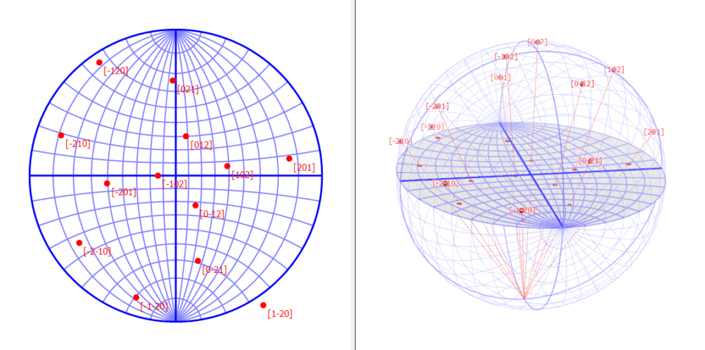
Equal-Area Projection