2.0. Overview
This window provides functions for expressing the crystal rotation state using a 3×3 matrix and converting between different Euler coordinate systems.
In ReciPro, the crystal rotation state is expressed by applying three Euler angles \(\phi,\theta,\psi\) in the order \(Z\)-\(X\)-\(Z\). However, this representation does not necessarily match the rotation axes of the goniometer in the actual laboratory optical system. By converting ReciPro’s Euler angles to Euler angles of any arbitrary definition, it supports goniometer adjustment in the laboratory.
2.1. ReciPro Coordinate System (ZXZ)
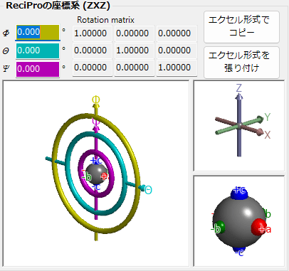
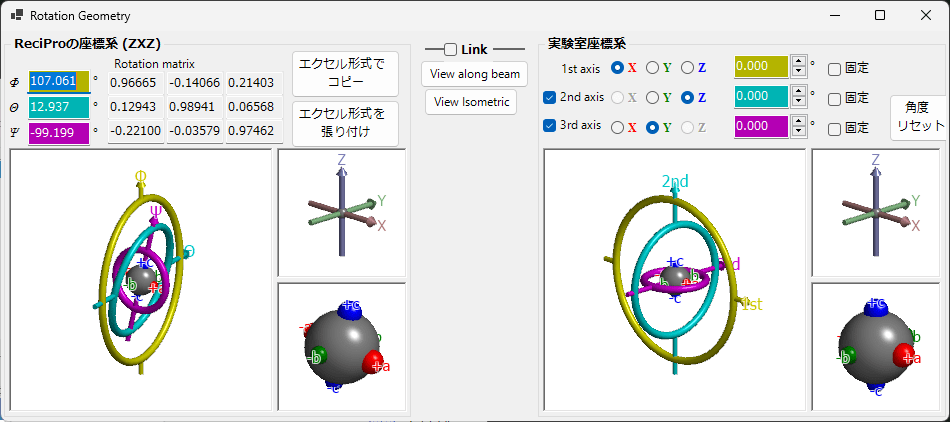
The left half of the screen is the section for displaying/setting the crystal rotation state expressed in ReciPro’s Euler coordinate system.
The \(\phi,\theta,\psi\) values displayed at the top are synchronized with the Euler angles in the Main Window. To change the \(\phi,\theta,\psi\) values, please do so from the Main Window side.
The “Rotation matrix” section displays the 3×3 rotation matrix corresponding to the current rotation state.
Copy in Excel Format
Copies the 3×3 rotation matrix to the clipboard in a tab-delimited format that can be pasted into Excel.
Paste Excel Format
When a 3×3 tab-delimited numerical matrix in Excel format has been copied to the clipboard, this sets it as the rotation matrix.
OpenGL Window
The OpenGL-rendered window displays a 3D visualization of the crystal’s rotation state.
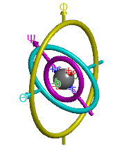
The screen showing three tori (thin donut-shaped objects) visualizes the state of the three rotation axes. The arrow passing through the yellow torus corresponds to the Euler angle \(\phi\) rotation axis, which is the upper (1st) rotation axis of the goniometer. The cyan arrow corresponds to the middle (2nd) rotation axis for \(\theta\), and the pink arrow corresponds to the lower (3rd) rotation axis for \(\psi\).
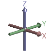
The screen in the upper right showing red, green, and blue arrows represents the X, Y, and Z axes in the real-space Cartesian coordinate system. Note that the arrows displayed on this screen are different from the arrows (crystal axes) shown in the Rotation control of the Main Window. Specifically, for the cubic, tetragonal, and orthorhombic crystal systems, a, b, c coincide with \(X,Y,Z\), but for other crystal systems, some of them do not coincide.
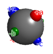
The gray sphere displayed at the center of the goniometer represents the state of the rotated object. The red, green, and blue spheres are markers indicating the orientation of this object1. When \(\phi,\theta,\psi\) are all zero, the red, green, and blue spheres are oriented in the \(+X, +Y, +Z\) directions of the real-space Cartesian coordinates, respectively. As the Euler angles change, the object rotates in various directions.
The OpenGL-rendered window accepts rotation operations via left mouse drag. However, note that this rotation operation does not rotate the crystal itself, but only changes the viewing direction. To rotate the crystal itself, perform the rotation operation from the Main Window side. For those who want to learn more about the coordinate system in ReciPro, please refer to the Appendix.
View along beam / isometric
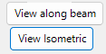
Pressing “View along beam” aligns the view with the projection direction of the Main Window. That is, the yellow rotation axis (the \(Z\) axis in the Cartesian coordinate system) becomes perpendicular to the screen2. “View isometric” projects from an oblique direction. Please note that it is the projection direction that is rotating, not the crystal.
2.2. Experimental Coordinate System
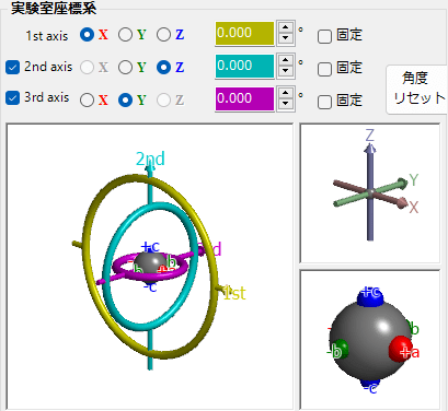
The right half of this window is the section for defining Euler angles with arbitrary rotation axes and displaying/setting the goniometer rotation state. This is called the “Experimental Coordinate System.” The explanation of the objects rendered in OpenGL is the same as described in “ReciPro Coordinate System” and is therefore omitted.
1st, 2nd, 3rd axes
For the goniometer rotation axes, please select from \(\pm X, \pm Y, \pm Z\) for each of the upper (1st), middle (2nd), and lower (3rd) axes3. When you switch the selection, the OpenGL window graphics will change accordingly. If the goniometer has only one or two rotation axes, uncheck the non-existent rotation axes.
The Euler angles for each rotation axis are displayed in the yellow, cyan, and pink text boxes. You can also enter values directly. Pressing the Reset button resets the entered rotation axes.
2.3. Link

Checking “Link” adjusts the Euler angles between the “ReciPro Coordinate System” and the “Experimental Coordinate System” so that the object orientation matches between them. In other words, it provides the Euler angle information for a goniometer expressed using rotation axes defined differently from ReciPro.
For example, suppose you have adjusted the laboratory goniometer so that the \(a\) axis of a crystal is aligned with the X-ray incident direction and the \(b\) axis with the horizontal direction. Using the following procedure, you can dramatically simplify goniometer operation in the laboratory:
- First, enter the Euler angles of the laboratory goniometer in the “Experimental Coordinate System.”
- Next, (with Link unchecked,) rotate the crystal in the ReciPro Main Window to align the \(a\) axis with the screen-perpendicular direction (beam direction) and the \(b\) axis with the horizontal direction.
- Check Link in this state.
- Rotate the crystal to any desired orientation in the ReciPro Main Window.
- The laboratory goniometer angles required to achieve that orientation will be displayed.